Blog by Jacek A. Rochacki
It is a pleasure to present this third article by Jacek Rochacki. In this article he is responding to a request that came up from several articles here on the blog about restoring Comoy’s pipes. In several of those pipes, particularly the Lumberman pipes, the stems were replacements. Jacek asked about putting the C logo on them. In this piece he gives the step by step procedure for inserting the C logo on a stem. Thank you Jacek for a helpful and timely article. It is greatly appreciated.
Let us begin from excerpt from A HISTORY OF COMOY’S AND A GUIDE TOWARD DATING THE PIPES, by Derek Green. It is published in Pipedia, unfortunately Derek’s internet pages do not exist anymore http://pipedia.org/index.php?title=A_History_Of_Comoy%27s_and_A_Guide_Toward_Dating_the_Pipes&action=edit
Inlaid “C”
“C” was first inlaid in the side of the mouthpiece around 1919. This was a complex inlay needing three drillings. First, a round white inlay was inserted, then the centre of the white was drilled out, and a smaller round black inlay was inserted. Finally, another drilling was made to remove the open part of the “C,” and an even smaller black inlay was inserted. This inlaid “C,” known as the “three-piece C,” was continued until the Cadogan era in the 1980s. However, the “C” in the 1920s and early 30s was much thinner and more delicate than the one post-war. Cadogan first changed the “C” to a single drilling with an inlay that had the “C” in the centre, and more recently it became a laser imprint. I have a cased pair of early 1920’ “Par Excellence” where the “C” is on top of the mouthpiece.
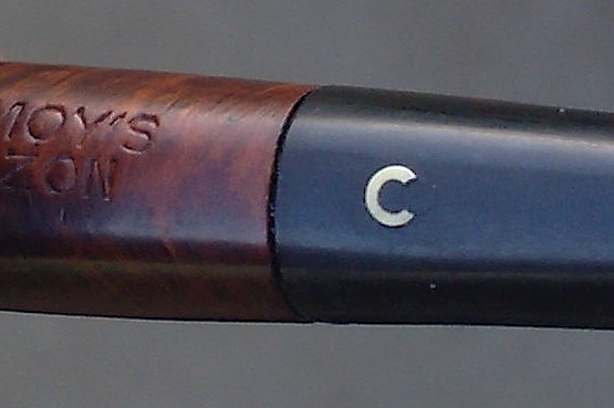
“Three piece C” on one of my Comoy’s
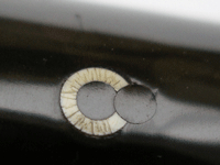
“Three piece C” originally published at the late Derek Green’s pages (sadly no longer existing today), the three elements are better visible here. Cracks on the letter “C” may be a subject for more detailed discussion; we remember such cracks in some old enameled objects, or in inlays of bone or ivory.
In order to follow this procedure the following essential tools are necessary:
– drill bit with sharp cutting edges of diameter corresponding with outer diameter of our “C” to be. I call it drill bit No. 1.
– drill bit with sharp cutting edges of diameter corresponding with inner diameter of our “C” to be. Let it be drill bit No. 2.
– drill bit with sharp cutting edges of diameter corresponding with diameter of this smaller black inlay that will remove the open part of the “C”. Let it be drill bit No. 3.
And: a jeweler’s frame saw, files, sandpapers, needle point marker, a drilling device possibly with regulation of rotation speed. Other tools like cutters, scraper, drills of other length and diameters may be of use. An old fashioned hand drill may be helpful because some operations on some materials should be performed at a very low speed.
First mark centre of our “C” to be. I do this using an ordinary needle fixed in a wooden handle but with tip slightly rounded. I heat the tip evenly with an ordinary lighter (I have been pipe smoker for years) and with this hot tip I mark a tiny hole, not deep, say, 0.2 mm. This centre mark will “guide” drill bit no.1. Just a few comments regarding drill bits: instead of using drill bits with ordinary/universal cutting edges shape there are other options that work well. Drill bits used in woodworking with “pilot” tip on them (brad point bits or dowelling bits) and Forstner bits of the correct diameter will work.
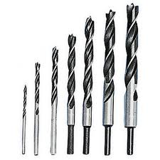
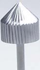
Brad point bits
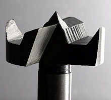
Forstner bit
Another method would be to drill “preliminary” hole with a thin drill bit (say 1.2 – 2.0 mm) and then continue drilling with a cutter like the one below used by jewelers/stone setters for setting precious stones.
Diamond setting cutter
Yet another way of drilling the holes would be to use cylindrically shaped cutter after drilling the “preliminary” hole. This “preliminary” hole should be just a little smaller than the outside diameter of the “C” we are making. The diameter of our cylindrical cutter must be exactly the same diameter as that of the outside of our “C”.
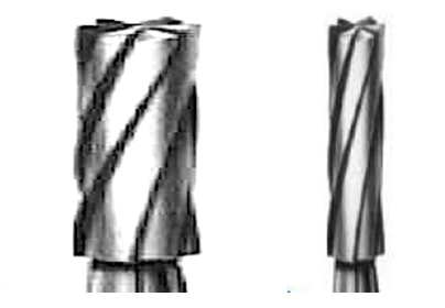
Cylindrical cutters
When we say “drilling” we have an understood association with a drilling machine. While that is true, let us stop here for a moment. What is a drill bit? It is just a cutter of specific shape, normally used for making holes. If we agree that it is some kind of cutter, then drilling is one of numerous processes within category of machining. http://en.wikipedia.org/wiki/Machining In our case we want to remove the material that we need in order to insert the “C” in a controlled way (subtractive manufacturing).
So the tool must be of proper shape and in best working condition = sharp! It would be going too far in this article to give a precise description on sharpening and maintenance of drills, but let us remember the necessity of using drill bits in best working condition. Basic information on drills including terminology is given on this site: http://en.wikipedia.org/wiki/Drill_bit#Twist_drill_bits
In some situations it is not necessary to operate drill bits or cutters with a drill/drilling device. If the bit is sharp and properly maintained etc., and we work with soft materials like vulcanite etc., it is sometimes OK to operate the drill bit with your fingers. The hole is created by drilling results from the sharpness and the right shape of cutting edges, not by using force. It is like carving with knife: the better and sharper the blade, the less force has to be employed.
When the hole is done/bored, we have to make the round white element to be inlaid. Ideally that would be a white vulcanite/material identical or well matching physical properties of the material of our stem, but I do not know if it is available today. Perhaps it might be found from this site: http://shop.hermanns.dk/group.asp?group=20
The best course would be to find a dealer who provides vulcanite in rods. If the diameter of the rod is bigger then what is needed, it is an easy job to thin it to our desired dimension by fixing a short piece in jaws of our drill (fixed in solid “horizontal stand) or in jaws that are fixed to our grinding/polishing machine, turn it on and while it turns use sandpaper to achieve required result. (I do not intend to convince all of us to begin learning simple turning – maybe we shall return to subject of turning vulcanite on another occasion, but a simple drill fixed in a horizontal stand, powered by electricity may serve as improvised lathe/turning machine!) .
When I had problems obtaining white vulcanite I remembered that it was available in acrylic. Acrylic is available in plates, rods, other forms. http://www.acrylite-shop.com/US/us/index.htm White opaque acrylic also works. If I had problems finding the required material in rods I use plates/sheets with a thickness of more than 3 mm. I cut the small disk of the required diameter with my trained, “sure” hand using a piercing saw or an even better idea would be to use a drill bit in the form of a short steel tube “crowned” with teeth, of inner diameter corresponding with diameter of the hole to be filled. It is the drill bit that reminds me of a hole saw bit without the “pilot” bit in the center.
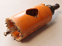
Original hole saw bit with “pilot”
At that time I was working and in constant touch with tool maker so I had my special tools custom made. But later in a distant place, in an improvised workshop, when I was in need of using such tool, I went to metal scrap and found a short piece of tube of hard metal of right diameter for my purpose. Steel would be good, but I learned that brass will also do because vulcanite and acrylic are soft materials. Using a jeweler’s triangular shaped needle file I made teeth, filed them to proper sharp cutting profiles and I had the “tube drill bit” that I need. Using this tool I was able to cut regular round elements.
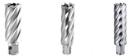
These pictures give a better orientation to the shape of cutting top/“crown” so please, do not pay attention to the “body” of this tubular cutting tool. Sorry, I am far away from my own workshop and tools so I don’t have exact photos of tools that I write about.
When I had finished making the disk/”peg”/round filling element I glued it in the hole and the first part of the work was done.
And one more thing: acrylic is also available in form of powder that is offered with hardener and creates solid material. This technique came to be popular in artistic silver jewelry during ’70s. So this provides another option. You would fill our hole with white acrylic powder, use the hardening liquid and precisely fill up our hole. Attention: some of these materials are of an “aggressive” nature. They sort of “melt in” the “walls” of places to be filled, thus the circle does not have a clean straight line/border but the line/border will look “shadowed”. Keeping this in mind I suggest that you get all the necessary information from the manufacturer or competent dealer on how the “border” between the filling and “mother” material will end up.
Continuing this idea: There are so called cold enamels used in contemporary cheap jewelry or sometimes in repairing objects that were enameled. And other colored artificial materials, some of them are hardened with ultra violet rays. Information on these products can be found here http://www.gesswein.com/p-896-colorit-set.aspx The site may give some orientation regarding this matter.
When our “white large spot” is ready (of course after the filling is hardened or, if glued the glue has created a solid “binding” we have to level it up with files and sanding and buffing etc.) we find and mark the precise center and make another hole by drill bit of proper diameter that I call drill bit No. 2. Then make a black ebonite (or other material the identical color of the stem) “peg”, mini disk or other element for filling using one of techniques mentioned above. This should give you a nice inlay of a white circle on the stem. Then again it involves sanding, buffing etc. to make the surface smooth.
Then mark precisely the place on the right side of the inlaid circle for using drill bit No. 3. Drill the hole and with another very small diameter pin or disk, using one of techniques described above, we “open” the circle giving it the shape of letter C. Then after the final sanding, buffing etc. voila – our inlaid C should be ready.
—
But it is possible to approach the subject in a slightly different way. Let us return to the beginning when we were drilling larger hole by drill bit No. 1. Remember what I said above on “tube”, or “tubular drill bits”. There may be a way to find the tube of hard metal of diameters exactly matching inside and outside diameters of our “C” and of walls of thickness corresponding with thickness of our “C”. In old metalsmithing/goldsmithing/silversmithing/coppersmithing etc. metal handicraft workshops we made short tubes ourselves using so called draw plates and draw tongs or a simple hand powered machine named draw bench. I say this as curiosity, I am far from trying to convince us all to become goldsmiths/metalsmiths, but perhaps a goldsmith performing old style handicraft – if such still exists – would make short piece of tube of brass of requested dimensions. When we have our improvised, but ideal dimensioned “tube drill bit” it should be not too difficult to bore/”carve” the approximately +2 mm deep (of depth) circle of dimensions of our “C” to be. The groove should be filled with powered acrylic or, perhaps better (I mentioned about some “aggressive” acrylics in form of powder) an element made of solid white material.
I would proceed as follows: I would cut/make this white strip of width larger than the depth of the groove taking into consideration the fact that our grooved “O” is carved on a concave surface. The thickness of this white strip should be of width of our groove – the final thickness of the letter “C”. Then I would “soften” this strip with hot water, steam or a heat gun, so that I could form it by using jeweler’s pliers with round conical tips or using as sort of mandrel piece of metal wire of proper diameter. Bicycle or motorcycle spokes of different diameters make very useful mandrels of small diameters. Using these tools I would shape the white strip in the form of circle/ring fitting the carved circle groove and I would glue it in place. After leveling operations such as filling, sanding, buffing etc., I would make the opening of this “O” to make required “C” out of it as I described above.
It would be easier to find a tube of white appropriate material (acrylite) of dimension that is set/determined by our circular groove – maybe something like a cocktail straw – but I am aware that chances are small, so I mention it just for completing indication /description of possible ways of proceeding.
—
All this is OK from the technical point of view, but there is another aspect to consider. This is the aspect of the authenticity of signature or logo. When making copy of an original there are ways of “marking” the final product so that it is clear that our work is a copy and not a falsification. One of ways of such “marking” is to make a small change of dimensions in comparison to original. Here our wish of having a “clear conscience” meets the eventual problems of finding drill bits and materials in rods of dimensions that correspond exactly with dimensions of original “C” on Comoy’s pipes. I believe that this is one of situations where these two aspects meet and stay together in harmony.

Hi! I have a Cadogan-era Comoy Rover with a C incised and painted on the stem. Is there a way to restore it? I’ve been searching your blog, because I know you mentioned re-inking a logo on a Kiko pipe, but I can’t find anything about how to do it.
I’m afraid to try brushing on India ink and wiping it off, because I’m worried it will soak in and leave a white blob. Any tips?
LikeLike
Good day, Lenny,
If I could have a chance of looking at precise photos of the signature (C incised) that needs to be restored, then perhaps I could be of some help.
LikeLike
Andrew just sent me this link to some great information on Comoy’s pipes. It is a google translate page.
http://translate.google.com/translate?hl=en&sl=zh-TW&u=http://www.piperepublic.org/t755-topic&prev=/search%3Fq%3DCadogan%2BEra%2BComoy%2527s%26start%3D20%26sa%3DN%26biw%3D1280%26bih%3D667
LikeLike
That is a pretty concise guide!
LikeLike
Steve, perhaps the dimension of this Comoy’s replacement C by Walker Briar Works are in “correspondence” with what I say in last sentences of my text ? It is difficult for me to believe that they could not acquire tools of desired dimensions; the size/dimension of our “C” is simple consequence of diameter of drill bits used. Unless somebody wants to make the “C” using this white tube to be fixed in the “O” carved groove and I may imagine that to find the drill bit of form that I call/name “tubular bit” and white material tube of required dimension may be a problem.
LikeLike
I gather that the smaller the dimensions, the more difficult the process becomes. Adam Davidson states in the Passion for Pipes blog entry linked above that the time necessary to create a small, factory sized logo is so intensive it is not economically feasible. Walker does this for an additional $15, so he has to take some shortcuts.
I have a Comoys stem with the 3 pc C logo, but it is broken. Is there a way to remove that insert and have it placed into a new stem? (like removing and reinstalling a GBD rondell). I’m guessing that is most likely not possible.
LikeLike
– if the original is really made of the three glued solid pieces and if we would find a way (solvent) that would make possible to separate glued elements leaving them intact, then, maybe, it would be possible. But it is just theory; in practice I am afraid that the gluing made bonding is of nature that makes impossible to remove inlayed element in their intact shapes/form.
In the world of old silver we often meet situation, where the original hallmarks with adjoyning area was cut off from old destroyed piece and soldered in proper place of the other object that then “pretended” to be as hallmarking says. Perhaps such procedure could be applied here, instead of soldering – use of glue and then making seams invisible ?
But if you happen to have all parts of this broken stem, then I would rather give a try to fix them together again by gluing and – if necessary – enforcing by some invisible element like I was trying to say in my text No. 2.
LikeLike
Ad dendum:
typo:
is: bonding is, should be: bondings
I absolutely agree with what @Adam Davidson says. Procedure of making such logo I would compare to precious stone setting. I understand that small dimension may make the operation difficult, but if it is conducted by tools of required dimensions wielded by trained sure hand and operation is conducted with constant use of/under magnifying glass faceplate, then after a couple of hours everything should be OK.
LikeLike
Great article! Its nice to learn new things about pipes, even though I don’t think I will ever try to make the 3 piece C.
Of more interest to me would be dealing with faded letter P on Peterson stems. Is there any way to deepen the P? Then typing “white out” can be used to fill in the groove, then sand. Maybe a heated blade or needle to deepen the P?
LikeLike
Dear Mark:
At first I would like to thank you dearly for your so kind words. I feel confused as I do not have pictures of stems with “C” logo made by myself that @upshallfan would like to see.
When dealing with faded letters/markings on stems at first I checked out if the letter/marking is pressed deep enough. If not, I was deepening it with my engraving tools/burins similar to these shown in my text no. 2 , kindly posted by Steve. But is some cases depending on the situation I was using technique of stamping, or rather, in case of vulcanite/ebonite stems, hot stamping. No, I did not made the complete stamp like P for Peterson or CP for Charatan, that would be separate topic, but I made of ordinary larger nail a stamp with working head of required shape or profile – straight line, curvature, any other shape that I needed for deepening lines of marking/letter at the stem. I have been making such simple stamps by precise filing and using proper abrasive and polishing tips at my flexible shaft machine. And during making stamp I was keeping at hand other piece of vulcanite and test stamping there I was constantly checking under magnifying glass if my stamp is getting required form. When it was ready, I heated it’s working head a little and, pressing with feeling I deepened part of marking/letter that required deepening. All this process was conducted under magnifying glass.
When the depth was right, it came time for white filling. I heard on usage of this typing “white out”, but I have been using simple and popular in old days zinc white diluted with drop of water to consistency of paste. That was used by engravers for creating white background that helped to see better the ornament to be engraved. Please, treat this as sort of curiosity, sort of “message from past days” 🙂 In recent years I was told about good results of usage of some cold enamel that I mentioned in this text but I did not used it for working with faded letters.
LikeLike
Correction:
is: cold emalia
should be: cold enamel
LikeLike
Jacek I edited your original post to read enamel!
LikeLike
Big Thank You 🙂
LikeLike
Jacek, do you think it is possible to deepen the etching with an electronic engraving tool? I wonder about the control of the tool as it seems to vibrate… worth trying I would think.
LikeLike
If the “working tip” is of required/appropriate width then yes, it sounds sensible. But please, first make test engraving on piece of vulcanite (other, perhaps broken stem). Some of such electronic engraving tools tend to make lines of not even, looking like “eaten up” edges. This is why I ask you: please, make test before purchase, I believe that in the shop they will allowe to connect the tool to electric socket and do some small test at piece of vulcanite that you will have with you. Then please, investigate/check results under magnifying glass.
LikeLike
Ad dendum: if the “tip” is removable, then the whole field for selfmalkig “tips” of shape and dimensions that we need openes…to be more specific I would have to know more on this particulat model of this electronic engraving tool.
LikeLike
Dear upshallfan:
In the field of pipe markings my works were rather small part of my educational line/teaching on falsifications of objects of applied art, where my lectures were accompanied by practical presentations and exercises in workshop. These samples that I made myself were serving as aids to theoretical lectures and practical exercises when we were working on real objects pointing out and investigating differences between originals and falsified pieces.
That was ca. 25 years ago and unfortunately I have no photo documentation; my fault…let me confess that at that time I did not thought that dealing with smoking pipes, being so easy in comparison to matters and restoration of historical silver and gold objects will become of interest for Fine People.
LikeLike
With computers and digital cameras, we take it for granted these days how easy it is to save photos. 25 years ago, it was a bit more challenging to save photo documentation. I bet even today, folks in attendance remember those presentations/lectures!
LikeLike
Thank you so much for your words full of understanding. Indeed, these of my former listener who are still alive are in constant contact with me; some of these who are foreign even decided to visit in me Poland after I decided to quit longer trips. They come not just out of courtesy but for some extra advices/consultation and we had so nice and fruitful time in my workshop. Up to now I am honored by people who need consultation, advivces etc. what is possible thanks to internet. And when the editor of my book on the Treatise on Goldsmithing by Benvenuto Cellini that I have been working on for ca. 40 years faced some financial problems, it were my former listeners who collected missing sum and just a couple months ago the book has edited in print.
LikeLike
IThanks for posting, I have not seen an article on this process, save Neill Archer Roan’s blog entry (Passion for Pipes) on a stem made by Adam Davidson:
http://www.apassionforpipes.com/neills-blog/2011/10/22/recreating-comoys-3-part-c.html
In the past few years, I’ve seen a few on various pipe forums, but the “C” is always too large (at least compared to the original.
Walker advertises a 3 pc C stem logo for $15 on his repair site, but I’ve never seen a picture of this work.
Please post any pictures of these stems, I find this process fascinating.
I’d also love to see pictures of the equipment Comoys used to make the stem at the factory, they seem to be non-existent.
LikeLike
Al, I have had Walker Briar Works do a Comoy’s replacement C for me and it was indeed larger than the original. It looks “okay” but not up to what I was expecting. That is why I am interested in learning how to do it myself and asked Jacek to elaborate on the process. It certainly looks doable!
LikeLike
I’d like to see what how it looks, can you post a picture?
LikeLike