This afternoon I received an email from Alan Chestnutt of reborn briar  regarding the second part of his blog article on Building a Buffing Station https://rebornpipes.wordpress.com/2013/12/17/the-building-of-a-buffing-station-alan-chestnutt/. He gave permission to post the second part here for folks to read about and also use for their own buffing stations. Thanks again Alan for taking time to answer the questions that were raised by readers of the blog following your first post. I am looking forward to reading their responses to your further update on the project. It is much appreciated. Just a reminder Alan has a website http://www.estatepipes.co.uk/ where he sells some of the beautiful pipes he refurbishes. This is how Alan makes a living and he does great work. He is available for working on pipes that you may not want to tackle on your own. Without further introduction here is Alan’s post.
Steve Laug had asked me to provide further information following some questions received on his blog about the buffing station. I will provide links to the items I bought in the UK to put this together. The items were purchased from eBay, so should be easy to pick up in any country.
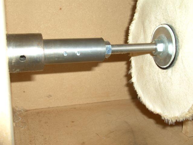
I had the arbor to connect the motor to the drive shaft machined locally in an engineering shop. There was already an extension shaft fitted to this motor which could not be removed. The drive shaft was wider than normal at 20mm and had a key way cut into it for the addition of a drive key. A normal motor drive shaft will look like the one below. If there is a drive key fitted in the shaft, it will pull out to leave the key way slot as shown.

The arbor was machined from 30mm steel bar. Half the length of the arbor was drilled to 20mm to allow it to be tapped over the existing shaft. Two grub screws were fitted which screw down into the key way slot for an effective connection.
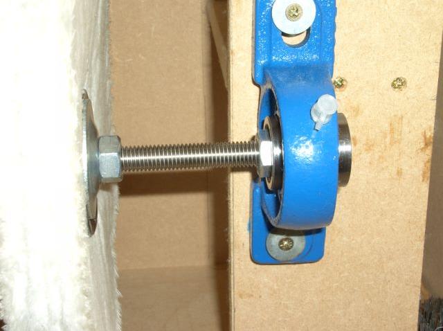
Each buffing wheel is screwed on to the centre of a 250mm length of stainless steel bar threaded with a 12mm metric thread. The buffing wheels are held in place on each side with a lock nut and the large cup washers which came with my bench grinder to hold on the grinding wheels before I stripped them down to convert them to buffers. I had these available, but any large washer with a 12mm centre hole would have done the trick. I bought the threaded rod from this link. http://www.ebay.co.uk/itm/300813988264
The second half of the arbor has a 12mm threaded hole. This allowed the first section of rod to be screwed fully into the arbor until it met the drive shaft of the motor, and it was then locked in place with a nut.
Each 250mm section of the threaded rod is joined together by screwing them into a 12mm threaded bush and then locked in place each side with a lock nut. http://www.ebay.co.uk/itm/181149210581
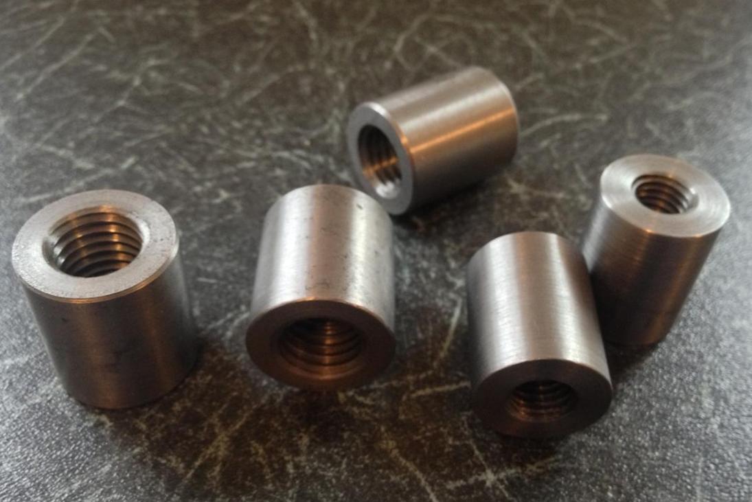
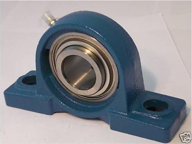
Each bush is then supported by a pillow block bearing as shown below. The external diameter of the bush matches the internal diameter of the bearing. Two grub screws on the bearing lock the bush in place to provide a smooth rotating shaft. http://www.ebay.co.uk/itm/320695884156
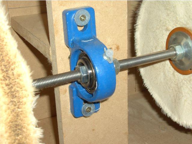
The end piece rod simply has the bush screwed on to it, secured with a lock nut and again supported by a block bearing.
Each piece connects together to form the completed unit as shown below. The upright supports for the bearings also provided the ideal platform to secure 2 batten light fixings fitted with strong daylight bulbs for good working visibility.
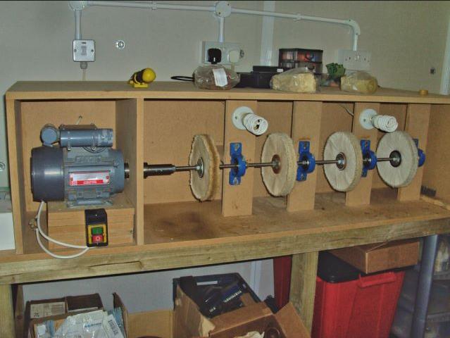
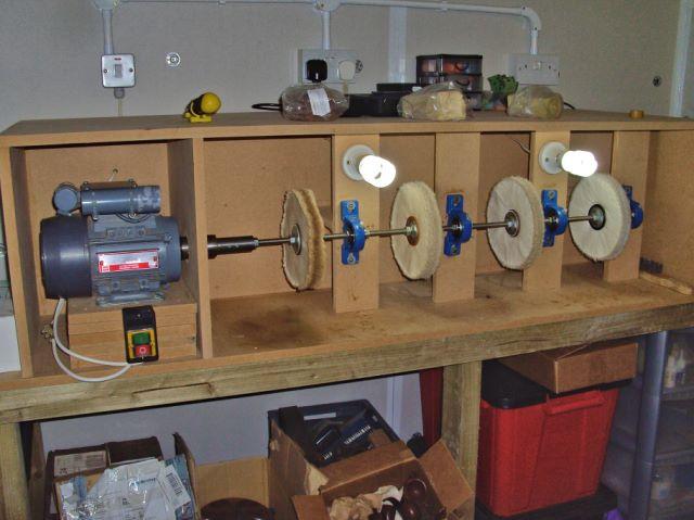
I opted for four separate sections of threaded rod as opposed to one long section to make it easier if I have to change an individual buffing wheel. I can easily isolate and detach the section required and attach the new buffing wheel. Fitting of a machine switch to the front allows me to easily switch the motor on and off. http://www.ebay.co.uk/itm/360736015048


Hi! I really need your help on converting a keyway motor shaft to fit a polishing wheel. I did not really understood how you tap the grub screw to the existing keyway slot. please i will really appreciate if you can leave a message on email!
LikeLike
What are the specs on your motor? Is it handling the longer shaft and multiple wheels? (since only one wheel at a time is used, I wouldn’t think it would have a problem with the longer shaft)
LikeLike
Al. The motor is a 0.75kw (1hp) cap start/run with a 1400rpm speed. It starts fast and has lots of torque and handles the 4 wheels no problem. The original idea came from Chris Askwith who runs a similar set up with one long drive shaft on an old lathe. I adapted the idea to use the 4 shorter shafts and the block bearings. My son has agreed to be taught in the art of pipe restoration so I may try using 2 wheels at once tomorrow, just to see how it copes.
LikeLike
A 1 HP motor should handle that load.
LikeLike
Really clever work! I might want more directional light, ie on a gooseneck and shade vs. those unshaded bulbs. I like how the pillow blocks have oil fittings, they should last forever. That is a very creative use of a single shaft motor and should serve you well for many years. Thanks for sharing via this detailed write-up.
LikeLike
Thank you Al. The bulbs in the lights are photography graded daylight bulbs and throw out a lot of bright white light. They light up the whole area and work well without shades. Other areas of the workshop could benefit from flexible arm lamps as I progress.
LikeLike